Digital Circuit Design (Part 1)
If you haven’t read the first post in this series, check it out here for the required context.
Introduction
In my last post I discussed the basics of the CPU cycle. CPUs are amazingly flexible devices as they enable programmers to run arbitrary code. This capability comes with its drawbacks. Namely, there’s significant overhead required to enable such flexibility. General purpose processors are remarkable feats of engineering, but let’s say we want to solve a problem under different constraints. Instead of optimizing for flexibility, what if we want to optimize for speed?
Problem Statement
Imagine you’re a hardware engineer working at a high frequency trading firm. Your colleague has written some code to implement a Moving Average Convergence/Divergence (MACD) trading strategy. Your job is to make it faster.
Aside: MACD
Moving Average Convergence/Divergence (MACD) is a simple momentum indicator frequently used to identify entry and exit points for trades. It works by keeping track of two moving averages: long term (usually ~26 days) and short term (usually ~12 days). The word “momentum” here is critical, as there’s a nice physical analogy. You can think of the long term moving average as having more “mass” and therefore more “momentum.” It takes more effort to change its velocity vector compared to the short term average. The MACD line is computed by taking the difference between these two moving averages, and a “signal line” is created by taking a 9 day moving average of the MACD line. Traders will use the convergence or divergence of these two signals to determine entry and exit points.
If you’re interested in learning more about MACD, you can read more here. How MACD is interpreted to make decisions is not important to understand the rest of this article, I mostly chose this example to motivate the material (as opposed to using the canonical example: traffic lights).
Ideation
Let’s break down the problem into its component parts: Consistent stream of data (stock price) Moving averages must be computed:
- 26-day long term moving average
- 12-day short term moving average
- 9-day MACD moving average (difference between the first two) Signals must be combined in some way to make decisions on when to buy and sell
Clearly we could continue to run this strategy using high-level code on a CPU. After all, your computer is very good at performing arithmetic. Those that read my last post, however, might be wondering why we need the CPU cycle at all.
Almost half of the CPU cycle is exclusively concerned with fetching and decoding instructions. In this case, we know exactly what algorithm we want to repeat each time. It seems like performance could be improved if the Fetch and Decode stages could be skipped. Instead of encoding our algorithm as a set of binary instructions stored and decoded by the circuit, what if we designed the circuit itself to only run our algorithm?
By designing a circuit from scratch to computing moving averages, we have effectively created a special purpose processor that only deals with execution and memory operations. No instruction fetching, no decoding logic, and no overhead in handling instruction ordering or code branches and jumps. Just a new circuit that does one thing: compute the average of a set of numbers.
Moving Average Circuit
The Simple Moving Average1 is defined as:
$$ SMA = \frac{(A_1 + … + A_n)}{n} $$
In English, add up all the samples and divide by the number of samples. Nothing fancy going on here. Now comes the hard part: how do we turn this into a digital circuit? Let’s start with some basics.
Aside: Notation
I find that notation tends to create large barriers to understanding complex topics. Let’s quickly go over a few useful pieces of notation used throughout the remainder of this post. Feel free to skip this section if you’re already familiar with logic gates, boolean algebra, and interpreting digital signals.
Logic Gates
Let’s introduce a couple basic logic gates.
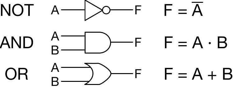
In the context of digital logic all inputs and outputs can be thought of as 0 or 1. On the left side is the circuit diagram notation, on the right is the written mathematical notation.
- NOT Gate: Simply inverts the input. $A = 1 \implies F = 0, A = 0 \implies F = 1$
- AND Gate: Outputs $1$ if and only if $A$ and $B$ are both $1$.
- OR Gate: Outputs $1$ if $A$ or $B$ is $1$
Digital Signal Plots
When analyzing digital circuits, it’s important to visualize how a signal evolves over time.
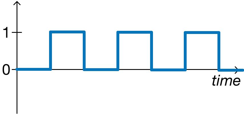
Digital signals are usually presented in this way, with time along the horizontal axis and the value along the vertical. We can see that over time, this blue signal oscillates at a regular frequency between zero and one. In other scenarios, we have a bunch of signals that together represent something else. For example, if we have 32 separate signals that represent at 32 bit integer, we might write that this way:
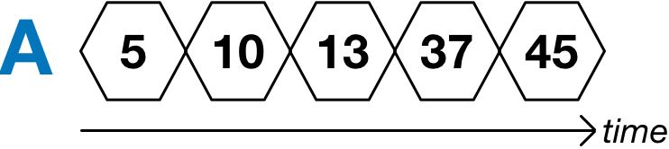
Instead of plotting 32 different signals to show $A = 00000000000000000000000000000101$ ($5$ decimal), we just write the decimal value and indicate the change using an “X.” Under the hood, all or some of those individual 32 signals are changing to now represent 10, then 13, then 37, etc.
Other Circuit Notation
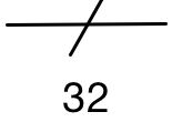
This notation indicates that a given line is actually 32 bits wide. The number 32 is arbitrary, the listed value just indicates the width of the line.
Types of Digital Circuits
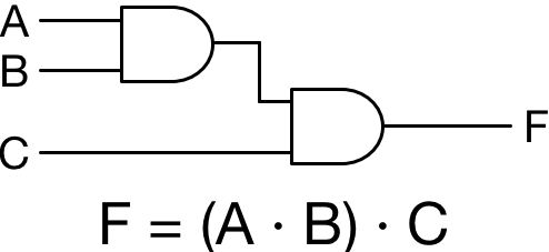
All digital circuits can be broadly reduced to two types: Combinational and Sequential. A combinational circuit has outputs that rely only on the current inputs. In the example below, the value of $F$ relies entirely on the current value of $A$, $B$, and $C$. You can think of inputs and outputs in this context as digital, so $0$ and $1$.
In contrast, a sequential circuit involves taking a combinational circuit and adding some memory element such that the circuit outputs don’t solely depend on the current inputs, but also the previous output state.
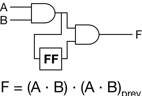
I’ve modified the above circuit to contain a memory element called a flip-flop (denoted FF). How this device works is not important right now, but just imagine that it stores the last input value for some amount of time. Now notice that the output of our circuit depends not only on the value of the boolean expression ($A \cdot B$), but also on the previous value. But wait, what does “previous value” even mean? How do we keep track of time?
System Clock
Keeping track of time is the job of the system clock. If you’ve ever gone through the process of purchasing a computer, you’ve probably compared different specs about its processor: amount of L1-L3 cache, number of cores, clock speed, etc. The system clock is just another digital signal, oscillating between zero and one at a certain frequency. That frequency is your clock speed. If you buy a 1 GHz processor, that means the internal clock signal is oscillating one billion (1,000,000,000) times per second!
The clock is important because it provides a notion of “before and after” in the context of digital circuits. All memory elements in sequential circuits update on the clock tick. In the example above, the “previous value” means the value at the previous clock tick. Let’s update our sequential circuit to include a clock signal as well as inputs and outputs to the memory element:
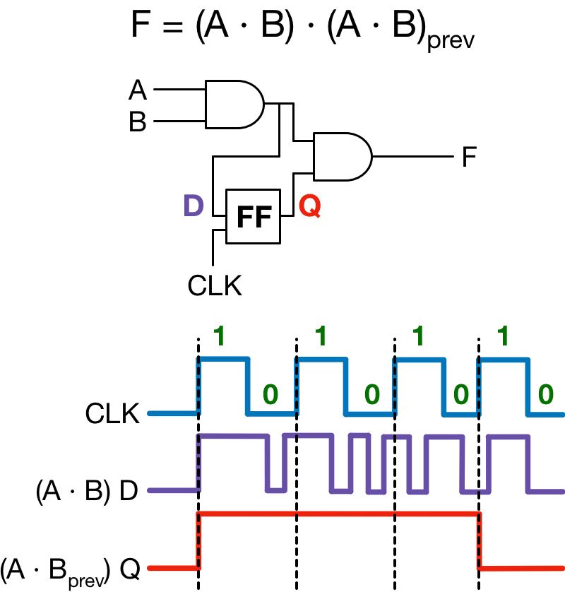
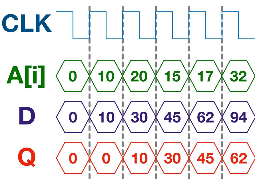
The key takeaway here is that the output $Q$ only updates on the positive edge of the clock (i.e. when it’s rising from zero to one). The combinational part of our circuit can fluctuate independent of the clock; once a positive edge is detected, the flip-flop will update its value to whatever $D$ is at that point. This is the value in sequential circuits: they allow us to save some state about our circuit, and use that state to generate new outputs.
Back to the moving average
With these basics in mind, it’s clear that we need some kind of sequential circuit to implement a simple moving average. Why? Let’s think about it. Referencing the equation for $SMA$, we have to perform n additions and one division. How might this be accomplished in a high level language? Maybe something like:
function sma(A, n) {
  int sum = 0;
  for (int i = 0; i < n; i++) {
	sum += A[i];
  }

  return sum / n;
}
Notice what we’re doing in that loop. We’re accumulating the sum by performing the ith addition and placing the intermediate result in a variable called sum. This is effectively a sequential circuit!
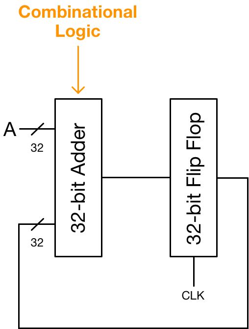
We can perform the exact same operation as the for loop by combining an adder circuit with a memory element. A 32-bit adder is entirely combinational, it’s an ensemble of basic logic gates. If we attach this adder to a memory element to store the sum, we can feed this value back into the adder as the second input. The adder now relies not only on the input $A$, but also on the previous value of the sum.
Let’s take a breath
Okay, that’s A LOT of information to process (no pun intended). Let’s take a step back and summarize (seriously, I’m not doing this on purpose). Everything we’ve designed thus far represents the “Data Path Unit” or DPU. As the name would suggest, this is the circuit through which our data passes, but that’s only half the story. There are a lot of unanswered questions: How do we know when to stop iterating? How do we load the appropriate value of A into the adder? I’ll answer these questions in the next section by designing the second half of every digital system: the control unit (CU).
Control Unit Setup
As I mentioned before, the Data Path Unit is only half the story. To create a single digital system to compute a simple moving average, we need to design a control unit. First, let’s add a few modules to our DPU:
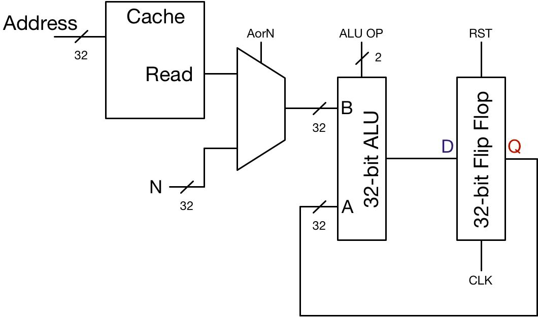
I’ve made some changes to our DPU and added a few new signals that are missing some connections. Here’s a breakdown of the changes:
- ALU instead of adder. Eventually we have to divide our sum by $N$, so we need a module capable of supporting multiple arithmetic operations. This comes with the addition of an “ALU OP” signal which can be set to indicate whether the ALU should do $A + B$ (0), $A - B$ (1), $A \times B$ (2), or $A / B$ (3).
- RST signal added to flip flip. The Reset signal simply resets the stored value to zero.
- Cache Module. Our function has two inputs: the array $A$ and the integer $N$ representing the length of the array. Before we run our addition, we will assume $A$ is loaded into a cache module with the first element at address $0$, the second at address $1$, etc.
- Input $N$. $N$, the length of array $A$, is also an input to this circuit. By input, I mean some external source is driving that line. If you want to use this module, you have to supply $A$ and $N$.
- Multiplexer to select between $A$ and $N$. AorN control signal selects between the two. $0$ to select $A$, $1$ to select $B$. Once we finish adding we’ll need to divide by $N$, so the input to the adder must switch.
In the next post we’re going to dive deep into state machines and the elements that make up a control unit. We’ll also touch on the process involved in bringing this circuit into production. Until then, if you’re looking for a challenge, try to design the state machine yourself using the DPU and control signals provided.
-
MACD requires an Exponential Moving Average. For simplicity we will design a circuit to compute the Simple Moving Average. Extending this circuit to implement an Exponential Moving Average is left as an exercise for the reader. ↩︎